The machine model implements a mechanical system with a single mass, but the mechanical torque node is available for manual connection of more masses. All machines are assumed to be linear.
ATPDraw embedded
In ATPDraw 5.7 the approach in Windsyn is directly embedded in ATPDraw without any external requirements.
Induction machine and synchronous machines appear as two separated components; UMIND and UMSYN respectively.
Both components are found in the Selection menu under Machines|Induction WU/Synchronous WU.
Both machines require manufacturers data, and offer flexible start-up options.
This component can be mixed with other Universal Machine components. The UM number is managed by ATPDraw and presented to the user in an disabled edit box. This number is used in the plotting program to identify the machine. There are no external files associated with the embedded windsyn variant and these components works as any other component (edit, grouping). $Parameters are disabled since the values are used in internal calculations. Consult the Universal Machine section of the RuleBook for restrictions for common bus and load.
Automatic start-up: ATP|Settings/Switch&UM. Specify Initial slip [%] (positive for motor)
Manual start-up (ramp): ATP|Settings/Switch&UM. Specify Initial load [pu] (positive for motor)
There is no need to recalculate parameters when changing start-up mode.
Compensation/Prediction: No changes required inside the model if solution method changes.
Both the induction and the synchronous machines have an embedded Governor for active power or speed control. The user can choose either simplified hydro or generic governors.
Induction machine
In the induction machine there is a fitting process based on power factor, efficiency, starting current and torque, rated current and slip and maximum torque. The fitting is automatically performed when the user clicks on the 'Fit & View' button. This brings up the induction machine fitting dialog.
To the left comes the 7 fitting parameters where the Entered values can be modified and the Fitted values are the best values possible. The user can tune the Weight values to modify the fit. Note that the external windsyn program relaxed the slip in the fitting of induction machines.
In order to get the expected power output, the rated current fitting is most important. Reducing the weight of the slip helps in fitting the other parameters (this is what always is done in the external Windsyn).
The default weight of the maximum torque (Tmax) is zero as this typically is the most uncertain parameter. To the right is the resulting electrical parameters used in the Universal Machine model.
The fitting is based on analysing the following circuits at start-up (Ist, Tst, s=1) and rated power (Is=1, pf, eff, s):
Rs Xs Xr Rs Xs+Xr
--/\/\/\--0000-----0000--- --/\/\/\--0000-----------------
0 \ 0 \ \
0 / 0 / / R2/s
Xm 0 R1/s \ Xm 0 R1/s \ 0
0 / 0 / 0 X2
-------------------------- -------------------------------
a) Wound and single cage rotors b)Double cage and deep-bar rotors
The following object function is minimized based on a gradient method:
OF(Xs,Xm,Rst,s)= w[1]*sqr(1-pfc/pf) + w[2]*sqr(1-effc/eff) + w[3]*sqr(1-Istc/Ist) + w[4]*sqr(1-Tstc/Tst) + w[5]*sqr(1-Is/1)+w[6]*sqr(1-s/slip) + w[7]*sqr(1-Tmaxc/Tmax);
where the index 'c' stands for calculated quantities and w[i] are the weights.
The stator resistance is not a free variable here as it is linked closely to the efficiency and the power factor. The equivalent rotor resistance at startup Rst is used in the fitting. The slip, s, is a free variable, possibly forced to the rated value, slip.
Start-up
For induction machines specify
Automatic mode: Initial slip in [%]. ATP will then detemine the torque source according to the initial load flow. With B-breaker > 0 this will result in a no-load start.
Manual mode: Initial torque in [pu] (positive for motor).
Brkwy torque [pu] is the friction torque at zero speed relevant for motor start-up only (positive torques). The load is modelled as TBrkwy*exp(-|w|/0.03)+TLoad*w^2, where w is the speed of the motor.
Extra load: Specify if an extra load in [pu] (positive for motor) is applied, when this happens and the ramp-up time in seconds.
The 'Start at rated speed' checkbox will in effect charge the intertia capacitance to its rated voltage. This give a faster reach of rated speed.
Synchronous machine
The calculation of electrical parameters is automatically performed when the machine data is written to the final ATP file. The Canay reactance is assumed equal to the leakage inductance and the zero sequence reactance is ignored. Calculation shown for round rotor with DQ dampers:
Zbase:=sqr(Voltage)/Power*1000
omega:=Frequency*2*Pi
Rs:= (1-Efficiency)*Zbase
Ls:= Xl*Zbase/omega
Lmd:= (Xd-Xl)*Zbase/omega
Lmq:= (Xq-Xl)*Zbase/omega
Lfd:= (Xd-Xl)*(Xd'-Xl)/(Xd-Xd')*Zbase/omega
Lkd:= (Xd'-Xl)*(Xd''-Xl)/(Xd'-Xd'')*Zbase/omega
Lfq:= Xq-Xl)*(Xq'-Xl)/(Xq-Xq')*Zbase/omega
Lkq:= (Xq'-Xl)*(Xq''-Xl)/(Xq'-Xq'')*Zbase/omega;//
If 'Rfd' is not given directly:
Rfd:= (Lfd+Lmd)/Td0
Rkd:= (Lkd+Lmd)/Td0''
Rfq:= (Lkq+Lmq)/Tq0
Rkq:= (Lfq+Lmq)/Tq0''
If 'If' is not given directly:
If:= Power/Voltage/(Xd-Xl)
Start-up
For synchronous machines specify
Automatic mode: Voltage in [%] and Angle [deg]. ATP will then detemine torque and field sources according to the initial load flow. With B-breaker > 0 this will result in a no-load start.
Manual mode: Torque in [pu] (positive for motor) and Field voltage in [pu]. The Calc button will estimate the field voltage based on the power factor and (estimated) values of If and Rf. To get the exact expected value of reactive power, the value has to be tuned somewhat and/or an exciter added.
The 'Start at rated speed' checkbox will in effect charge the intertia capacitance to its rated voltage. This give a faster reach of rated speed.
Extra load: Specify an extra load in [pu] (positive for motor) is applied, when this happens and the ramp-up time in seconds.
Exciter Two different types are included (DC1 and ST1) with diagrams available under /Exciter/View.
The user can choose either voltage or reactive power in [pu] as set-points.
WindSyn external
For backward compatibility the old external Windsyn_ATPDraw support is maintained
The Windsyn component class in ATPDraw consists of two components; WisInd.sup and WisSyn.sup for induction and synchronous machines respectively. Both components are stored in the standard component library; atpdraw.scl. Default values for the machine parameters are given in these files.
The connection to Windsyn has to be set up under Tools|Options/Preferences as the WindSyn command.
The user can either specify the machine parameters directly in ATPDraw or in Windsyn. The user can also directly select the type of machine as listed above. If the user switch from induction to synchronous machine or vice versa, a new machine model is initalized.
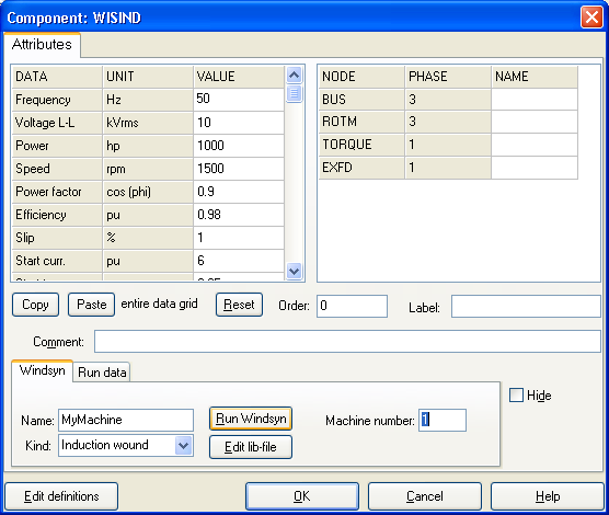
The input dialog of the Windsyn component in ATPDraw.
In order to use the Windsyn component in a data case the user has to run the Windsyn program via the Run Windsyn button. Then the input file to Windsyn atpdraw.wis is created and Windsyn executed. While Windsyn is running the text "Windsyn is running (ESC)" is displayed. ATPDraw waits for Windsyn to terminate befor reading in the result files. The waiting process can be interupted by pressing the escape key. This might be needed if Windsyn terminated incorrectly. In Windsyn the user can change the machine model and in the end create new output files (Save Data followed by Exit). The output/result files are then automatically loaded by ATPDraw and a $include file is created as seen when clicking the Edit lib-file button. It is possible to directly import a lib-file here and thus omitting the Windsyn step. The final lib-file is dumped to disk in the ResultDir with a name specified in the Name field (do not enter path or '.lib' as this is added automatically). The ResultDir is the same location as the ATP-file. As all lib-files (user specified, lcc and windsyn) are dumped to this directory file name conflicts can occur if components of different class have the same name. See the prefix options under Tools|Options/View/ATP.
In the Run Data page the startup parameters for the machine are specified. These are dependent on the type of machine and initialization method as given in ATP|Settings/Switch/UM.
The machine number is the present number of this universal machine. The number is the sequence the machine is written in the ATP file. This number must be used when adding external control to the machine. The machine number is a dynamic quantity that can change as the the circuit develops; machines deleted or new machines added.
Windsyn adds a TACS control module to the machine. In this model there are a number of predefined names not dummy declared. So watch out for unexpected name sharing. In all cases the machine number is added at the end of the node names as indicated with the 'n#' character. This can be a two digit parameter.