|
Harmonic frequency scan and load flow components.
The Harmonic Frequency Scan (HFS) is one of the options under ATP | Settings / Simulation. General load flow specification is given under ATP|Settings/Load flow. |
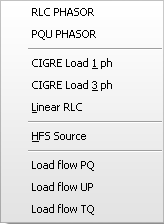
Selection |
Object name |
Icon |
ATP card |
Description |
RLC Phasor |
RLC_PHASOR |
|
BRANCH |
RLC component only present during steady-state (t<0) |
PQU Phasor |
PQU_PHASOR |
|
BRANCH |
RLC component only present during steady-state (t<0) |
Cigre load 1 ph |
CIGRE_1 |
|
BRANCH type 0 |
Single-phase CIGRE load |
Cigre load 3 ph |
CIGRE_3 |
|
BRANCH type 0 |
3-phase CIGRE load |
Linear RLC |
RLC_F |
|
BRANCH type 0 |
Linear RLC for HFS studies |
HFS Source |
HFS_SOUR |
|
SOURCE type 14 |
Harmonic frequency source |
Load flow PQ |
LF_PQ |
|
SOURCE Load flow |
Load flow component with active and reactive power restriction |
Load flow UP |
LF_UP |
|
SOURCE Load flow |
Load flow comp. with voltage and active power restriction |
Load flow TQ |
LF_TQ |
|
SOURCE Load flow |
Load flow component with angle and reactive power restriction |
|
Selecting HFS under ATP | Settings / Simulation will run the ATP data case so many times as specified in the Harmonic source component dialog box. The frequency of the harmonic source will for each ATP run be incremented. In the example shown at left, 5 harmonic components are specified in the F/n column, and the ATP data case will run 5 times.
|
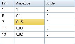
In the first run the source frequency will be 1x50 Hz, the second run 5x50 Hz etc. up to the fifth run f = 11x50 Hz = 550 Hz. The Freq. value specified by the user under ATP | Settings / Simulation is used here as base frequency. The source frequency can also be specified directly in Hz and in such case the first F/n must be greater or equal to the Power Frequency. Specifying the frequencies F/n like 50, 250, 350, 450, and 550 would be equivalent to what is shown in in the figure above.