The type of input is set by clicking on the nodes and specify the type. The default type (which is node voltage) can also be set under Edit Definitions.
ATPDraw can read a mod-file/Model description and identify input/output and data, with indices and default values. ATPDraw accepts either comma or CR+LF as separation between variables. Comment flags 'C' in column 1 and '--' are handled as well as comment..endcomment.
Plotting of Model variable can be achieved in two ways. Models Output can be monitored by the Models probe (Selection|Probes&3-phase), Models internal variables can be monitored with the RECORD option. From version 5.4 this is found in the Model's input dialog by clicking the Record button in the MODEL input dialog.
MODELS Order. If the output from one Model is used as input to another, the first Model must be declared first in the ATP file. This is enforced by given the first model a lower Order number in it's dialog and then use the ATP|Settings/Format - Sort by Order.
The manual methology
1. Creating the model file
The example in this chapter is taken from example 14 in the ATPDraw distribution. It illustrates indexed outputs. The Model calculates the harmonic content of an input signal X using a recursive DFT procedure.
MODEL FOURIER
comment
Calculates the Fourier series factors and outputs the absolute value
and angle of the harmonics of the input signal X.
Analytical Fourier integrals based on the Trapzoidal rule.
endcomment
INPUT X --input signal to be transformed
DATA FREQ {DFLT:50} --power frequency
n {DFLT:26} --number of harmonics to calculate
OUTPUT absF[1..26], angF[1..26],F0 --DFT signals
VAR absF[1..26], angF[1..26],F0,reF[1..26], imF[1..26],i,NSAMPL,OMEGA
D,F1,F2,F3,F4
HISTORY
X {DFLT:0}
DELAY CELLS DFLT: 1/(FREQ*timestep)+1
INIT
OMEGA:= 2*PI*FREQ
NSAMPL:=1/(FREQ*timestep)
F0:=0
FOR i:=1 to 26 DO
reF[i]:=0
imF[i]:=0
absF[i]:=0
angF[i]:=0
ENDFOR
ENDINIT
EXEC
--window X?
f1:=delay(X,(NSAMPL+1)*timestep,1)
f2:=delay(X,NSAMPL*timestep,1)
f3:=delay(X,timestep,1)
f4:=X
F0:=F0+(f4+f3-f2-f1)/(2*NSAMPL)
FOR i:=1 to n DO
D:=1/(i*PI)*((f4-f2)*sin(i*OMEGA*T)-(f3-f1)*sin(i*OMEGA*(T-timestep))
+(f4-f3-f2+f1)/(timestep*i*OMEGA)*
(cos(i*OMEGA*T)-cos(i*OMEGA*(T-timestep))))
reF[i]:=reF[i]+D
D:=1/(i*PI)*((f4-f2)*cos(i*OMEGA*T)-(f3-f1)*cos(i*OMEGA*(T-timestep))
-(f4-f3-f2+f1)/(timestep*i*OMEGA)*
(sin(i*OMEGA*T)-sin(i*OMEGA*(T-timestep))))
imF[i]:=imF[i]+D
absF[i]:=sqrt(reF[i]**2+imF[i]**2)
IF abs(imF[i])<1E-10
THEN
angF[i]:=0
ELSE
angF[i]:=atan2(imF[i],reF[i])
ENDIF
ENDFOR
ENDEXEC
ENDMODEL
The model file must be given a name with extension .MOD and it is preferrably stored in the \MOD folder. In this example the name FLASH_1.MOD was chosen. The name of the model file must be the same as that of the actual model.
2. Creating an ATPDraw object manually
An ATPDraw object consist of a file on disk which is called a support file, with extension sup. A support file is standard for all components in ATPDraw and contains the icon, information on node types and position and on data parameters. For a Model the support file is optional (from version 5). It can be created and used for cases when the user wants the Model's icon and node positions to be predefined. The support file is created manually under Library/New/Model/sup-file.
To create a new a support file manually, enter the Library/New menu and select sup-file under Model. The standard sup-file editor appear where the definitions can be set. The user can specify the number of input+output (=node) and data and the name of these parameters. The numbers and names must exactly match what is defined in the Model's header.
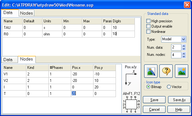
Fig. 1. Support file editor for Models.
Data
Set Param to 1 is $Parameter is allowed for this data.
Set min=max if no range checking is to be performed.
Digits is not important.
Default is the default value.
Units is a 12 character optional text string.
Node
The Kind is a code for the type of parameter:
Kind MODELS Description
0: output
1: (i) current input
2: (v) voltage input
3: (switch) switch status input
4: (mach) machine variable input
5: (tacs) tacs variable input
6: (imssv) imaginary part of complex steady-state node voltage
7: (imssi) imaginary part of complex steady-state switch current
8: output from other model
9: (atp) input of global ATP variable (MNT=simulation number)
#Phases can range from 1 to 26. The syntax in the Mod-file is X[1..n], n=1..26.
Pos.x & Pos.y is the relative node positions. x from left to right, y from top to bottom. Values from -120.. 120 is supported. The positions must be rounded off the the nearest 10. For bitmap icons the values -20, -10, 0, 10, 20 are used. The standard x positrion is -20 on the left side and +20 on the right side.
Model objects also must have an icon which represents the object on the screen and an optional help which describes the meaning of parameters. If you need your own help file click the
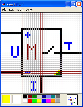
Fig. 2. The icon of the new model object
Finally, when you click the Save or Save As buttons the support file of the new model object will be saved to disk. A file window appears where you must specify the name of the object. The support file should have the same name as the mod-file (if any). The support file should have the extension .SUP and preferrably stored in the \MOD folder. You can reload and modify the support file of the model objects whenever you like, using the Model|sup-file item in the Library|Edit menu.
The new model object has now been created and it is ready for use. It can be found in the component selection menu under the MODELS field. After you have selected this field, a file window appears where you can select the file FLASH_1.SUP. This will draw the Model and it can be edited like any other ATPDraw objects.