To use the built-in line/cable module of ATPDraw the user must first select LCC Template under Line/Cable item in the selection menu. The input dialog of the LCC object is shown in Figure 1. Using the Internal Parser all data in the LCC object can be given a Variable name assigned globally and in this way study the effect of parameter changes.
System setup
The same input dialog is used for system types Overhead lines, Single core cables, Enclosing pipe and Matrix Import and this is the first thing the user must consider. The LCC object can hold data for all these types at once so in theory it is possible to switch between the system types. To the top right on the Model page the entire content of the LCC object is shown in a tree structure.
The number of phases are specified in the dialog box (#Phases). From version 7, an integer number (2G=2147483647) of phases is supported, in 3-phase or single-phase view. A single support file LCC.SUP is the basis for all LCC objects.
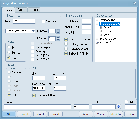
Figure 1 Line/Cable data dialog
Template-Section mechanism
An LCC object can be a template and used by a component called LCC section (LCC_). When an LCC object is a template is is not written to the ATP file, has no node connections and 'template' is written in the icon. The LCC section object have Length, Freq and Rho data parameter and this optionally (v7.5 allows the user to inherit the Freq and Rho data of the template) replaces the standard parameters given in the LCC template. In the LCC section object, the user has to select the template and optionally give name to the UseAs string. The final pch-file will get the name template_useas.pch (if no UseAs name is given a unique number will be assign to it). When the LCC template object changes, the icon of LCC section objects are automatically updated. Se also the LCC section dialog.
Creating the model
When the required data are specified the user can close the dialog by clicking on OK. This will store the specified data internally in the data structure. If there are changes in the model, the user is asked if a new model should be executed to produce the required punch file or internal data. If the user answers No to this question, the model is created when writing the final ATP file under ATP|Make file or ATP|Run ATP. The user can also modify the icon of line/cable (Edit icon), but this is overwritten if the number of phases #Phases is changed since the default icon then is reloaded.
It is very important to ensure a correct ATP installation and setup of the ATP command in ATPDraw. This is done under Tools|Options under Preferences. It is recommended to use batch files. Two such files will be distributed with ATPDraw (runATP_G for the recommended GNU version and runATP_W for the Watcom versions). If the setup of ATP is incorrect, line and cable models will not be produced. When creating a Noda line/cable model the Armafit program is executed automatically to create the required lib-file. The Armafit command is specified under Tools|Options under Preferences. The batch file runAF.bat is distributed with ATPDraw. Since all files are written to ResultDir, the ATP|Settings/Format $Suffix and $Prefix cards could always be inserted.
The Line/cable dialog consists of three pages (where the line and cable page overlap):
Model data page
Line data page overlapping
Cable data page overlapping
Matrix Import page
Node page added to version 5.3.
System type:
•Name: Name of the object and final lib-file. Must be unique for objects not sharing lib-files.
•Template: If checked the object becomes a template (not written to the ATP-file). Add LCC section objects to use the template (with length, freq, and rho variations). Many LCC sections can share the same LCC template and changes in the cross section is made only in the template.
•Number of phases: 1-2G (=2147483647).
•Overhead line: LINE CONSTANTS
•Single core cables: CABLE PARAMETERS
•Enclosing pipe: CABLE PARAMETERS
•Matrix import: Import series impedance and shunt admittance as function of frequency in XML format.
Standard data:
•Rho: Ground resistivity
•Freq: Frequency of model. Starting-frequency of JMarti, Semlyen, Noda and ULM models.
•Length: Length of line/cable in m or km as given.
•Internal calculation: Parameters internally calculated. Enables ULM and Matrix Import.
•Set length in icon: Length in m or km added to the icon
•Single phase icon: All nodes laid out as single phase
•Embed in ATP-file: Punch file embedded in the the final ATP file instead of using $INSERT
Object content:
Tree structure with the overhead/cable/matrix data
Model:
•Bergeron: Constant parameter KCLee or Clark models
•PI: Nominal PI-equivalent (short lines)
•JMarti: Frequency dependent model with constant transformation matrix
•Noda: Frequency dependent model
•Semlyen: Frequency dependent simple fitted model (not supported in CABLE PARAMETERS)
•ULM: Frequency dependent phase domain model. Enabled if Internal Calculation is checked.
View:
Displays the cross section of the specified line or cable.
Zooming is supported with speed- or mouse- buttons (in: left, out: right).
Copying to the Windows clipboard is supported in either bitmap or metafile formats.
For Matrix Import the series impedance and shunt admittance is plotted instead as there is no geometry to show.
Selecting this button will establish a LINE MODEL FREQUENCY SCAN or a Power Frequency Calculation data case. Further ATP is executed and ATPDraw reads the generated LIS file and displays the result. This enables the user to compare his line/cable model with an exact PI-equivalent as a function of frequency, or verify the power frequency benchmark data for zero/positve short circuit impedances, reactive open circuit line charging, and mutual zero sequence coupling. The LINE MODEL FREQUENCY SCAN feature of ATP does not work for Noda models.
With the Internal Calculation checked and JMarti or ULM models used, Verify shows the fitting of characteristic impedance/admittance, modes of the propagation matrix H= exp(-sqrt(Y*Z)*l) and overall fitting with accuracy and pole numbers given at the end. The ULM model might need some optimization of fitting parameters, see Internal Calculation.
Run ATP
This will request the name of the component (can also be used to change the name) and execute ATP to produce a puch file automatically transformered into a Data Base Module file (ResultDir+ComponentName+.LIB). This file is added to the final ATP file via the $Include command. If the user do not execute ATP in the dialog it is executed later when the final ATP file is created. This is generally not recommende since it this could be difficult to figure out which LCC module failed.
OK button
This will store the specified data internally in the data structure. If there are changes in the model, the user is asked if a new model should be executed to produce the required punch file or internal data. If the user answers No to this question, the model is created when writing the final ATP file under ATP|Make file or ATP|Run ATP. The name of the component is mandatory and is written in the header of the LCC dialog. The name of the component will be the name of the punch file created in the ResultDir directory and is added to the ATP file via a call to $INSERT. Using Embed in ATP-file will not write the punch file to disk.
The user is given a warning and thus get a chance to Cancel the operation and change the name of the component if the multiple instant was unintended.
Import/Export
These buttons are used to import or export the LCC data from/to an external library. The default extension is alc file (atpdraw line/cable) and the preferred location is the /LCC directory.
Edit defin.
This buttons shows the Edit Definitions/Support dialog. Here the user can edit the icons and specify a local help string. Be aware of that the icon will be overwritten if the number of phases changes. The Node information is also easily overwritten.