In this page the data for all cables in the system is specified.
The cable number is selected in the top combo box with a maximum number specified in Num. cables in the Model page. The data for one cable can be copied to an internal clipboard and pasted into another cable. The number of conductors per cable (core-sheath-armor) is selected on the right side in Figure 1 for each cable. ATP requires sorting of the cables with those having most conductors to be specified first, ATPDraw will do this sorting automatically, but the user can also sort the cables for better overview and control.
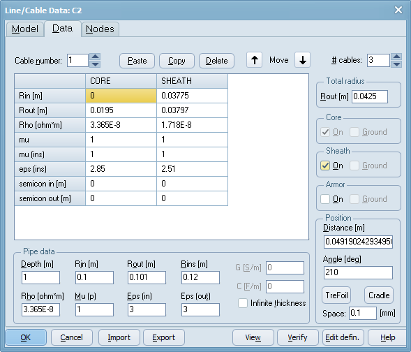
Figure 1 Line/Cable dialog, Cable Data page
For each of the conductors Core, Sheath and Armor specify:
Data |
Description |
Rin |
Inner radius of conductor [m]. |
Rout |
Outer radius of conductor [m]. |
Rho |
Resistivity of the conductor material [ohm*m]. |
mu |
Relative permeability of the conductor material. |
mu(ins) |
Relative permeability of the insulator material outside the conductor. |
eps(ins) |
Relative permittivity of the insulator material outside the conductor. |
Semicon in |
Thickness of inner semiconductor layer in [m]. |
Semicon out |
Thickness of outer semiconductor layer in [m]. |
Gext |
Extra conductance per length added between the conductor and the next layer. |
Cext |
Extra capacitance per length added between the conductor and the next layer. |
Rout tot. |
Total outer radius of cable, including the outer insulation layer [m]. |
The semiconductor quantities are normally only specified for the Core. It is the user's responsibility to make sure these thicknesses in sum are less than the insulation thickness Rtotal-Rcore_out or Rsheat_in-Rcore_out. The semiconductor layers are used to calculate a modified permittivity for the insulation.
If Cable Constants is checked, the user can ground conductors manually to match the number of phases given. If not, Cable Parameters is used and this will automatically ground the cable system from the outside. View will draw grounded conductors in gray color with conductor number zero.
The position of each cable is given in the lower right corner. For single core cables the absolute x-y position is given in [m]. The y-position must be positive regardless of location in air/ground set in the System Type. The x-position is arbitrary as only the difference between cables are used in calculations. For enclosing pipe cables the distance [m] and angle [degrees] related to the pipe center are given instead. For 3-cable systems for both types of cables there are TreFoil, Cradle location calculators available. For pipe type cables, TreFoil locates the cables around the center of the pipe, while Cradle locates the cables at the bottom of the pipe. The cables are located compact with Space separation distance in [mm]. For Single core cables, both TreFoil and Cradle compacts the cable around the depth specified in the first cable.
Specify also
Data |
Description |
Total radius |
Total radius of the cable (outer insulator) [m]. |
Conductors |
Turn on optional Sheath and Armour conductors. |
Position |
Positive positions relative to ground surface for single core cables and relative to pipe center for enclosing pipe. |
For Cable Parameters the NGRND parameter (number of grounded conductors) are calculated internally in ATPDraw based on the total number of conductors in the system and the number of initially selected phases. For Cable Constants the user must specify which conductor to ground by checking the appropriate Ground buttons. A warning will appear if a mismatch between the number of phases and the number of ungrounded conductors is found. Grounded conductors are drawn with a gray color under view.
For Enclosing Pipe type cables specify also the Pipe characteristics:
Data |
Description |
Depth |
Depth of pipe (positive value). Specify air/ground in System type |
Rin |
Inner radius of pipe [m]. |
Rout |
Outer radius of pipe [m]. |
Rins |
Outer radius of pipe insulation [m] |
Rho |
Resistivity of the pipe material. |
mu |
Relative permeability of the pipe material. |
eps (in) |
Relative permeability of the insulator material inside the pipe. |
eps(out) |
Relative permittivity of the insulator material outside the pipe. |
Gext |
Extra conductance per length added between the pipe and ground. |
Cext |
Extra capacitance per length added between the pipe and ground. |
Go to Overview of line/cable modelling.